
|
| Home | Downloads | Screenshots | Forums | Source code | RSS | Donate |
| Register | Log in |
| < Quick bugfix update for WindowsBugfix0ring streak > |
|
The DS GPU and its fun quirks Oct 27th 2018, by Arisotura |
|
Oh hey, another 'technical shito' post. Kind of a preamble to what will be the flagship feature of 0.8. (would be nice to add actual tags/categories to this blog, btw. heh) Anyway, I want to talk about how the DS GPU works, how it's different from modern GPUs, and why I don't think that using Vulkan over OpenGL would be any benefit. I don't know Vulkan a lot, so don't quote me on that, but from what I get, Vulkan stands out by working on a lower level than OpenGL, letting you manage the GPU memory and similar things. This may be good for emulating more modern consoles, where sometimes proprietary graphics APIs are used that allow levels of control that aren't possible with OpenGL. For example, the blargSNES hardware renderer -- one of the tricks it pulls is that during some of the operations, the same depth/stencil buffer is used with different color buffers. This isn't possible with OpenGL. Also, there's less cruft between the application and the GPU, meaning better performance, provided you're doing things right. While OpenGL drivers are full of optimizations for common use cases and even for specific games, with Vulkan it's all up to the application to be, you know, well programmed. So basically, with more power comes more responsibility. I am no 3D API expert, so, back to what we know well: the DS GPU. There are already a few posts about specific parts of it (the fancypants quads, the viewport shito, a fun rasterizer quirk, the wonderful antialiasing implementation), but here we're going to cover the whole things, with all the juicy details. Or atleast all those that we know of. Heh. The GPU in itself is a fairly old and obsolete piece of hardware. It is limited to 2048 polygons and/or 6144 vertices per frame. The resolution is 256x192. Even if you increased that by 4, performance would not be a concern. The DS can output a maximum of 122880 polygons per second under optimal conditions, which is puny compared to modern GPUs. Now, we get into the details of the GPU operation. It looks fairly standard on the top, but deep down the operation is different from modern GPUs, which can make it difficult to emulate some features properly. The GPU is split in two parts: the geometry engine and the rendering engine. The geometry engine processes incoming vertices, builds polygons and transforms them so they can be passed to the rendering engine, which (you guess) draws them to the screen. The geometry engine Fairly standard geometry pipeline. A detail worth noting is that all the arithmetic is done using fixed-point integers, as the DS doesn't support floating-point numbers. The geometry engine is emulated entirely in software (GPU3D.cpp), so it's not too relevant to what we use to render graphics, but I'm going to detail it anyway. 1. Transform and lighting. Incoming vertices and texture coordinates are transformed using sets of 4x4 matrices. Lighting is optionally applied to vertex colors. Pretty standard stuff there, the only nonstandard part is how texture coordinates work (1.0 = one texel on the DS). We can also note the whole matrix stack system, which is more or less a hardware implementation of glPushMatrix() et al. 2. Polygon setup. Transformed vertices are assembled into polygons, which can be triangles, quads, triangle strips or quad strips. Quads are natively handled and not converted to triangles, which is a bit of a problem as modern GPUs only support triangles. However it seems that someone came up with a solution which I will have to test out. 3. Culling. Polygons can be eliminated based on whether they're facing the screen and which culling mode is selected. Pretty standard too. I have yet to determine how this works for quads, though. 4. Clipping. Polygons that are outside of the view volume are eliminated. Polygons that are partly outside are clipped, this step doesn't create new polygons but can add vertices to the existing ones. Basically, each of the 6 clipping planes can end up adding one vertex to the polygon, which means we can end up with as much as 10 vertices. The part about the rendering engine will explain how this is dealt with. 5. Viewport transform. X/Y coordinates are transformed to screen coordinates. Z coordinates are transformed to fit within the depth buffer's 24-bit range. An interesting bit would be how W coordinates are handled: those are 'normalized' to fit within a 16-bit range. For this, each polygon's W coordinates are considered, and if any is greater than 0xFFFF, they are shifted right by 4 until they all fit within 16 bits. And conversely, if they're all less than 0x1000, they're shifted left until they get there, presumably to get better ranges and thus better precision for interpolation. 6. Sorting. Polygons are sorted so that translucent polygons are drawn last. Then they are sorted by their Y coordinates (yes), which is mandatory for opaque polygons and optional for translucent ones. This is also why it's limited to 2048 polygons: it has to store them somewhere to perform the sorting. There are two internal memory banks dedicated to storing polygons and vertices. There is even a register telling you how many polygons and vertices are stored. The rendering engine This is where the fun begins! Once all the polygons are all set up and sorted, the rendering engine begins its work. First fun thing is how it fills polygons. It's nothing like modern GPUs, which seem to fill by tiles and use algorithms optimized for triangles. I don't know how all of them work (heh), but I have seen a bit of how the 3DS GPU does it, and it's tile-based. Anyway, on the DS, it's a scanline renderer. They have to do it this way so that it can render in parallel with the oldschool 2D tile engines, which operate on a per-scanline basis. There is a small buffer of 48 scanlines which can serve to even out overload on some scanlines. The rasterizer is a scanline-based convex polygon renderer. It can handle arbitrary amounts of vertices. It can render things wrong if you give it polygons that aren't convex or that have crossed edges, for example:  A butterfly polygon. All fine and dandy. What happens if we rotate it, though?  Oops. What went wrong there? Let's outline the original polygon to get an idea: 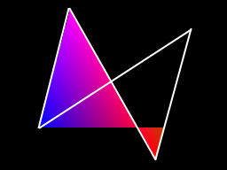 The renderer is only able to fill one span per scanline. It determines the left and right edges starting at the topmost vertices, and follows those edges until it meets new vertices. In the picture above, it starts from the topmost vertex, the top left one, and keeps filling until it meets the end of the left edge (the bottom left vertex). It is unaware that the edges are crossing. At this point, it looks for the next vertex on the left edge, noting that interestingly, it knows not to pick vertices that are higher than the current one, and also knows that the left and right edges have been swapped. Thus, it continues filling until the end of the polygon. I'd also picture some examples of non-convex polygons, but we're drifing away here, you guess how those go. Instead, you probably wonder how Gouraud shading and texturing can work with arbitrary amounts of vertices. There are barycentric algorithms that work for interpolating things over a triangle, but... yeah. The DS renderer, once again, does its own thing. More fancy pics to describe it.  The polygon vertices are points 1, 2, 3 and 4. The numbers don't match what the actual winding order would be, but you get the point. For the current scanline, the renderer determines the vertices that directly surround the edges (as said above, it starts with the topmost vertices, then walks the edges until they end). In this case, those vertices are 1 and 2 for the left edge, 3 and 4 for the right edge. The edge slopes are used to determine the limits of the span, which are 5 and 6. The vertex attributes at these points are interpolated, based on the vertical positions within the edges (or horizontal positions for edges whose slopes are X-major). With that, for each pixel within the span (for example, point 7), the attributes at that pixel are interpolated from the attributes previously calculated at points 5 and 6, based on the X position within the span. The factors used here are all 50% to make things easier to deal with, but you get the point. I'm not getting into how attributes are interpolated in detail, this would be beyond the scope of this post. Although this would be interesting to write about too. It is basically perspective-correct interpolation, but there are some fun shortcuts and quirks. Now you know how the DS fills polygons. How about the actual fill rules now? This is a bunch of fun too! Yeah. Well, first of all, there are different fill rules for opaque and translucent polygons. But the killer detail is that the rules are applied per pixel. Translucent polygons can have opaque pixels, and those will follow the same rules as opaque polygons. You guess how this goes -- emulating this kind of shit on a modern GPU requires separate rendering passes. Then, various polygon attributes can affect rendering in various fun ways. Additionally to the pretty standard color and depth buffers, the renderer also has an attribute buffer, which keeps track of all sorts of fun things. Namely: polygon IDs (separately for opaque and translucent pixels), whether a pixel was translucent, whether it should receive fog, whether it is from a front-facing or back-facing polygon (yes), and whether it is on the edge of a polygon. And maybe more. Emulating this sort of thing is not going to be trivial. Your average GPU has a stencil buffer that is limited to 8 bits, which is not nearly enough to emulate all the things the attribute buffer can store. So we will need to think of clever workarounds for this. Let's see: * depth buffer update: it is mandatory for opaque pixels, optional for translucent ones. * polygon IDs: polygons are assigned 6-bit IDs, that can serve a few purposes. Opaque polygon IDs are used for edge marking. Translucent polygon IDs can be used to control where those are drawn: a translucent pixel will not be drawn if its polygon ID is the same as the existing translucent polygon ID in the attribute buffer. Both polygon IDs also serve to control where shadows are drawn, in a similar fashion, so for example you can have a shadow that covers the floor but not your character. (side note: shadows are a simple stencil buffer implementation, nothing too terrible there) Worth noting that when drawing translucent pixels, the existing opaque polygon ID is preserved, as well as edge flags from the last opaque polygon. * fog flag: determines whether the fog pass should be applied to this pixel. How it is updated depends on whether the incoming pixel is opaque or translucent. * front-facing flag: this one is a bastard. If you happen to remember: 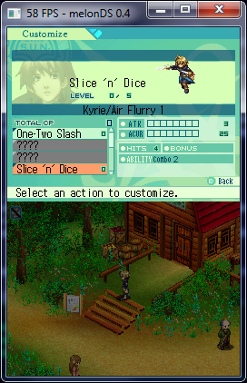 (oh, what a lazy ass, she reused old screenshots for this) Sands of Destruction, living up to its name. The screens in that game are quirk alley. Not only do they do things like tweaking their Y coordinates to influence Y-sorting, the screen shown in that screenshot is probably the worst. It relies on a depth test edge case: the 'less than' compare function accepts equal values when you're drawing a front-facing polygon over opaque back-facing polygon pixels. Yes. As the polygons' Z values are all zero, the screen will be missing elements if you don't emulate this quirk. I guess the intended effect was that you'd want your object's front side to always be visible over the back side, even if it's so flat that the Z values are all the same. The DS renderer feels like a hardware version of those DOS-era renderers in that it's full of hacks and quirks like that. Anyway, this will be tricky to emulate with a GPU. And there are other similar depth test edge cases that have to be tested and documented, too. * edge flags: the renderer keeps track of where polygon edges are. These serve for the final passes, namely, edge marking and antialiasing. There are also special edge filling rules for opaque polygons when antialiasing is disabled. The following graph, made from an old image I found, describes these rules:  Side note: wireframe polygons are rendered by only filling the edges! How smart. A fun note on depth buffering, too: On the DS, you get two possible modes for depth buffering: Z-buffering and W-buffering. Seems quite typical. Of course that's without getting into the details. * Z-buffering uses Z coordinates, transformed to fit within the 24-bit range of the depth buffer. The Z coordinates are interpolated linearly across polygons (with a few oddities, but that shouldn't matter). Nothing too atypical there. * W-buffering uses W coordinates as-is. Typically, modern GPUs seem to use 1/W instead, but, y'know, the DS uses fixed-point arithmetic, so using reciprocals wouldn't be a very good thing. Anyway, in this mode, the W coordinates are interpolated with perspective correction. And, finally, the final rendering passes, in order: * edge marking: the pixels that have edge flags set are given a color, taken from a table and determined based on the opaque polygon ID. This will color polygon edges. Noting that if a translucent polygon was drawn over an opaque polygon, that polygon's edges will still be colored. Side effect of how clipping works: the borders where polygons intersect with the screen borders will also be colored. You can notice it for example in Picross 3D screenshots. * fog: it is applied per-pixel, based on depth values which are used to index a fog density table. You guess, it is applied where fog flags in the attribute buffer are set. * antialiasing: it is applied to the (opaque) polygon edges. Pixel coverage values are calculated during polygon rendering, based on edge slopes. During the final pass, those pixels are blended with the pixels below, via a clever mechanism that was described in a previous post. Antialiasing doesn't need to (and cannot) be emulated this way on a GPU, so this doesn't matter here. Except for the fact that if edge marking and antialising are to be applied to the same pixels, they only get edge marking but with 50% opacity. I guess we have more or less well described the rendering process. We didn't get into texture blending (combining vertex and texture colors), but this can be emulated with a fragment shader. Same goes for edge marking and fog, provided we can find ways around the whole attribute buffer thing. But regardless, my point there is that OpenGL or Vulkan (or Direct3D or Glide or whatever) will not make a difference here. Our modern GPUs have more than enough power to handle the raw polygons. The issue is all the rasterization details and quirks. It's not even about pixel perfection here, just take a look at DeSmuME's issue tracker for example to see the issues they're facing with OpenGL rendering, the same issues which we will have to tackle somehow. As a side note, going with OpenGL would have the advantage of allowing it to be ported to, say, the Switch (as Github user Hydr8gon started making a Switch port of our emulator). Well... wish me luck. (fun reminders of the blargSNES times, where I initially thought that hardware rendering was impossible... and you know how that went) |
| 16 comments have been posted. |
| < Quick bugfix update for WindowsBugfix0ring streak > |
| Pages:12 |
|
HELLO says: Aug 27th 2023 |
| vulkan |
| Pages:12 |